Vinyard1 project protocol
Survey of maximum gape (jaw-opening) and condyle measurements for 21 inbred strains of mice (2009)
Vinyard CJ, Payseur BAProject protocol — Contents
Workflow and sampling
Equipment and supplies
Procedures
Data
References
Workflow
Mice are euthanized and weighed balance scale body weight Jaws of each mouse are manually opened to measure gape handheld caliper maximum gape Superficial tissues surrounding the head are removed and jaw muscles are digitally photographed and images stored for later retrieval dissecting tools, stereomiscroscope, computer, digital image analysis software masseter muscle (dorsal and ventral) attachments to condyle distances Lower jaws muscles and tissues are dissected and removed, remaining tissues on the bones are cleared enzymatically dissecting tools, temperature controlled water bath After calibrating SigmaScan with eyepiece micrometer, skeletonized right mandibular bones are digitally photographed and images stored for later retrieval stereomiscroscope, computer, digital image analysis software Scanned images are labeled according to 6 points of interests (Fig.3); metric analyses are then conducted using a digital image analysis software stereomiscroscope, computer, digital image analysis software mandibular length and condyle features: length, heights, articular surface angle • CO2 compressed gas and euthanasia chamber
• Balance scale, Mettler PJ400 (0.01g)
• Two pairs of sliding calipers: one is used to open the jaws and locked them in place, the other is used to measure gape (Mitutoyo)
• Small animal dissecting instruments
• Ruler, reticles or eyepiece micrometers for calibration
• Trypsin
• Temperature controlled water bath
• Digital camera attached to stereomicroscope (Leica MZ7.5)
• Digital image analysis software (SigmaScan Pro 4.01)
• Computer processor
a. Shortly upon arrival to the animal facility, the mice are sacrificed by trained personnel using CO2.
b. Before postmortem rigidity (rigor) occurs, body weight and maximum gape are measured.
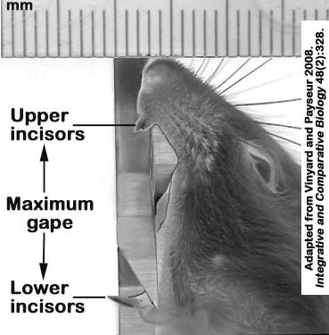
c. To obtain maximum gape, the mice are positioned such that the jaws can be manually opened to their maximum capacity without excessive force using two pairs of sliding calipers (one is used to open the jaws and locked them in place, the other is used to measure gape). While the jaws are retracted, the maximum jaw gape is measured as the linear distance between the upper and lower incisors, see Figure 1 below.Submitting Investigator's note: "This measure estimates the maximum structural capacity for jaw opening rather than a performance captured during a specific behavior (e.g., an activity with an explicit biological role)."
Figure 1. Schematic illustration of measuring maximum jaw gape.
d. The skin and subcutaneous tissues are then undermined and removed using dissecting scissors. Under stereomicroscope the location of the masseter muscles in relation to the entire head is exposed and digitally photographed. In order to preserve metric accuracy, each photograph is calibrated with a ruler image when used in SigmaScan.
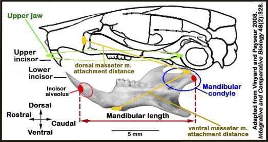
e. The position of the masseter muscles on the jaws, specifically the dorsal and ventral attachments of the superficial masseter and the locations of their insertions in the condyle, are digitally analyzed and quantified using SigmaScan Pro, see Vinyard and Payseur 2008, and Figure 2 below. These morphometric analyses can be done anytime, once the images are calibrated, captured, and stored into a computer for later retrieval.Figure 2. Medial-view photographic illustration of the right mandible relative to the position of the head. Note the extent of the upper jaw is demarcated in green, the lower jaw in red and the articular condyle in blue. The dorsal and ventral attachments (origin) and distances of the superficial masseter muscles to the condyle are drawn in yellow.
f. After obtaining and storing digital photographs of the jaws with the head still attached, the jaws are then disarticulated from the head and the surrounding muscle tissues are dissected and removed.
g. The jaws or mandibular bones are then skeletonized by enzymatic digestion using trypsin. This is done by placing the dissected jaws in water bath containing trypsin maintained at 24°C to 37.8°C temperature for a few days until remaining tissues are completely digested and easily removed.
h. After the jaws are completely cleared, the skeletonized mandibles are usually separated at the mandibular symphysis during the process, thus making up the right and the left mandibular bones, see Figure 3A below.
i. The right mandibles are positioned in medial-view and digitally calibrated and photographed as before using the stereomicroscope.
j. Captured images are then stored in a computer for later retrieval and thorough morphometric analyses by the same person.
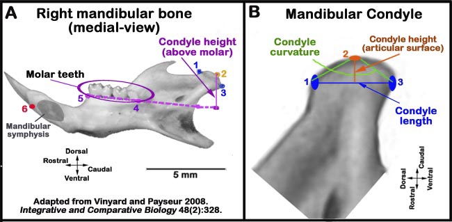
k. Scanned digital images of the right mandibles are labeled according to 6 points of interests (1 = anterior-dorsal limit of the condyle; 2 = highest point on the condyle; 3 = caudal-ventral limit of the condyle; 4 = caudal-dorsal limit of the third molar (M3, tooth) alveolus; 5 = anterior-dorsal limit of the first molar (M1) alveolus; 6 = anterior-ventral tip of the incisor alveolus), see Figure 3A below.
l. Using the pre-calibrated and pre-labeled digitized images of the right mandible and SigmaScan Pro software, the length of the mandible is measured from point 6 to point 3, see Figure 2 above.
m. Likewise, the length of the condyle is measured from point 1 to point 3, see Figure 3B below.
n. Similarly, the height of the articular surface of the condyle is measured from point 2 forming a perpendicular line with a line created between point 1 and point 3, see Figure 3B below.
o. As above, the overall height the condyle above the molar tooth row is measured from point 2 forming a perpendicular line with a line created between point 4 and point 5, see Figure 3B below.
p. Finally, the angle of the curvature of the condyle is measured from the angle formed by points 1-to-2-to-3, see Figure 3B belowFigure 3. A. Skeletonized medial-view of the right mandible showing 1- 6 points of interest used for morphometric analyses. B. Closer view of the mandibular condyle and the different features of interests.
Data collected by investigator
• maximum gape: distance between upper and lower incisor tips at maximum passive jaw opening [mm], see Figure 1 above.
• mandibular length: distance from the incisor alveolus to the caudal surface of the mandibular condyle [mm], see Figure 2 above.
• dorsal and ventral masseter attachment to condyle distances, see Figure 2 above.
• mandibular condyle length: length of rostral-caudal condylar articular surface [mm], see Figure 3A above.
• mandibular condyle height above molar: height of the condyle above the molar tooth row [mm], see Figure 3A above.
• mandibular condyle height of articular surface [mm], see Figure 3B above.
• mandibular condyle angle of curvature [°], see Figure 3B above.
Definitions and calculations
Masseter muscle: primary skeletal muscle for mastication-by raising the mandible and closing the jaws. Superficial origin: maxillary zygomatic process and caudal border of the zygomatic arch. Deep origin: caudal border and medial surface of zygomatic arch. Superficial insertion: angle and ramus of the mandible. Deep insertion: dorsal half of ramus and lateral surface of coronoid process of the mandible. It is innervated by the trigeminal cranial nerve (CN V).